
Scuba regulators have come a long way since the days of the old double hose design of the 1950’s. Today even the low budget units breathe with far less effort than the best of the old time regulators. Modern regulators have gotten good, really good. Space age materials, computer numerical machining, and modern manufacturing techniques have done wonders for breathing performance, reliability, and maintainability. Aside from these major advances, probably the two things that have helped improve regulators the most in recent years are the European CE Directives, which mandates performance testing, and engineering test standards. Also, the wide spread use of the ANSTI breathing simulator, which allows manufacturers to precisely test and analyze the equipment being developed by removing much of the guess work and extensive prototyping.

In a perfect world, the amount of effort required to breath from a scuba regulator during a dive would be no greater than breathing on land without a regulator. However, it is not a perfect world. During a dive, the increased density of the breathing gas due to the water pressure and the energy required to activate gas flow, and keep it flowing, as well as the energy required to force the exhalation gas out into the water makes the amount of effort to breathe underwater far greater than on the surface. In the early years of regulator development, regulators were tested by simply using them. In the early years of open circuit the depth limit in the US Navy was set at 130 FSW primarily because of breathing performance and the lack of good breathing performance. To dive deeper than 130 FSW on a double hose was extremely risky.

In earlier years, only the US Navy had the sophisticated and expensive equipment needed to scientifically measure an breathing apparatus performance. The equipment and system(s) were far too expensive for manufacturers and the personnel with the required skills to conduct the testing were rare. In the world of sophisticate unmanned performance testing, the Navy reigned supreme. From the 1970’s to the mid 1990’s, Navy testing put pressure on manufacturers to improve performance. Manufacturer’s regulators that met the stringent Navy requirements had bragging rites and a shot at being placed on the coveted, Authorized for Navy Use List (ANU). Just having a regulator tested by the Navy was a valuable marketing tool for any manufacturer. Aside from spurring manufacturers to work harder to improve regulator performance, Navy testing did little to help in the engineering and development of scuba regulators. The Navy mission was / is not to develop equipment, but only to test and evaluate it for Navy suitability. The Navy unmanned test reports give work of breathing data, but do not make raw data available to the manufacturers. Additionally, the Navy considers their computer programs for work of breathing to be proprietary and does not allow manufacturers or non-government test facilities to share the software. This has made it difficult for manufacturers to improve equipment based on the Navy’s testing or test methods.

In the early 1990’s, things in the world of equipment testing started to change. A small engineering company, ANSTI, from outside Portsmouth, England introduced a specially designed, highly accurate test system designed for manufacturer’s development and testing. These ANSTI systems have become the world wide standard as far as test systems go. Equipment designers who do not have access to one find it very difficult to compete with those that do. Because of these systems, not only has regulator performance gotten better, but also manufacturing reliability has been vastly improved.

How well a regulator performs is based on several primary factors including diving depth, breathing rate/tidal volume and the mechanical and flow characteristics of the regulator.

Diving Depth: The deeper the dive the denser the breathing gas resulting in a greater resistance in flow during both inhalation and exhalation.

Breathing Rate: Tidal Volume is the amount of gas moved in and out of the lungs with each breath. Combining the tidal volume and the number of breaths per minute (bpm) is known as Respiratory Minute Volume (RMV).

Mechanical and flow characteristics of the regulator includes:

  • The ease of which the inlet valve cracks and allows the flow to start
  • Smoothness of air delivery
  • Keeping positive pressure to a minimum
  • Low exhaust resistance

All these characteristics are a balancing act in the design of a regulator. To make a regulator perform well at the high breathing rates often causes a sacrifice in breathing performance at the lower, normal breathing rates.

During inhalation, the effort required to start air flowing is called cracking effort. The cracking effort as well as the effort required to keep the gas flowing is inhalation effort. The ability of a diver to do heavy exertion is directly proportional to how well the regulator can supply and exhaust the breathing gas. As breathing resistance increases, the divers ability to work at higher exertion levels decreases.

The modern breathing simulator is a rigid, mechanical device integrated with pressure transducers and sensors linked to a computer. The highly sophisticated breathing simulator can mimic typical human breathing rates (breaths per minute) and volumetric displacement (lung volume). This breathing simulation is not exactly like human breathing, but it’s pretty close and does allow very accurate scientific measurements to be taken under controlled conditions. These measurements can be reliably duplicated at a later date with the same or other simulator systems.

The simplest way to visualize how a breathing simulator works is to think of a piston within a cylinder. The piston moves back and forth within the cylinder at a set distance known as the stroke. The piston diameter and stroke determine the volume displaced during one stroke. One stroke during inhalation and one stroke during exhalation make one complete breathing cycle. The stroke of the breathing machine can be adjusted according to the lung volume to be simulated and the number of strokes per minute can be increased or decreased to simulate the number of breaths per minute (bpm). Most breathing systems can be varied from 10 bpm to as much as 40 bpm. For European CE testing, the stroke used is 2.5 liters with a breathing rate of 25 bpm resulting in 2.5 liters X 25 bpm = 62.5 Respiratory Minute Volume (RMV). One half of the breathing cycle rate is inhalation and one half is exhalation. The complete cycle is known as the loop.

So how does this equate to a diver? Typically, the average fit male open circuit scuba diver can swim along at a moderate work rate of 35-40 RMV for at least five minutes. Military rebreather divers routinely swim long distances (1-2 miles) while maintaining 40-50 RMV. A scuba diver moving slowly taking in the scenery may take about 15-20 (bpm) and the breathing volume will average between 1.5 to 2.5 liters. For breathing simulator-testing purposes, if the breathing rate is 10 to 20 (bpm) a 2-liter tidal volume is normally used. For 25 bpm a tidal volume of 2.5 liters is normally used and for 30 bpm or greater, a tidal volume of 3.0 liters is normally used. Exactly how and why the actual volumes are used can vary according to the breathing characteristics being simulated. The ability to test over a wide range of volumes and rates allows the breathing simulator to identify the full capability of the equipment being tested.
The Breathing Simulator

When evaluating how much effort is required to breathe, the breathing simulator is the final word. Subjective human testing cannot take the place of a collection of sensitive instruments. However, it must be understood that breathing simulators lack the compliant volume that a human has, and can actually induce certain characteristics that are not present when a human breathes. This is why some breathing loops at shallow depths show sharp increases and decreases in pressure shown as spikes on the loop. In effect, the breathing loop shows the true pressure readings over stroke travel (volume). These readings are reproducible and are extremely valuable in determining the characteristics of the apparatus. Along with breathing machine testing, manned diving will substantiate final capability.

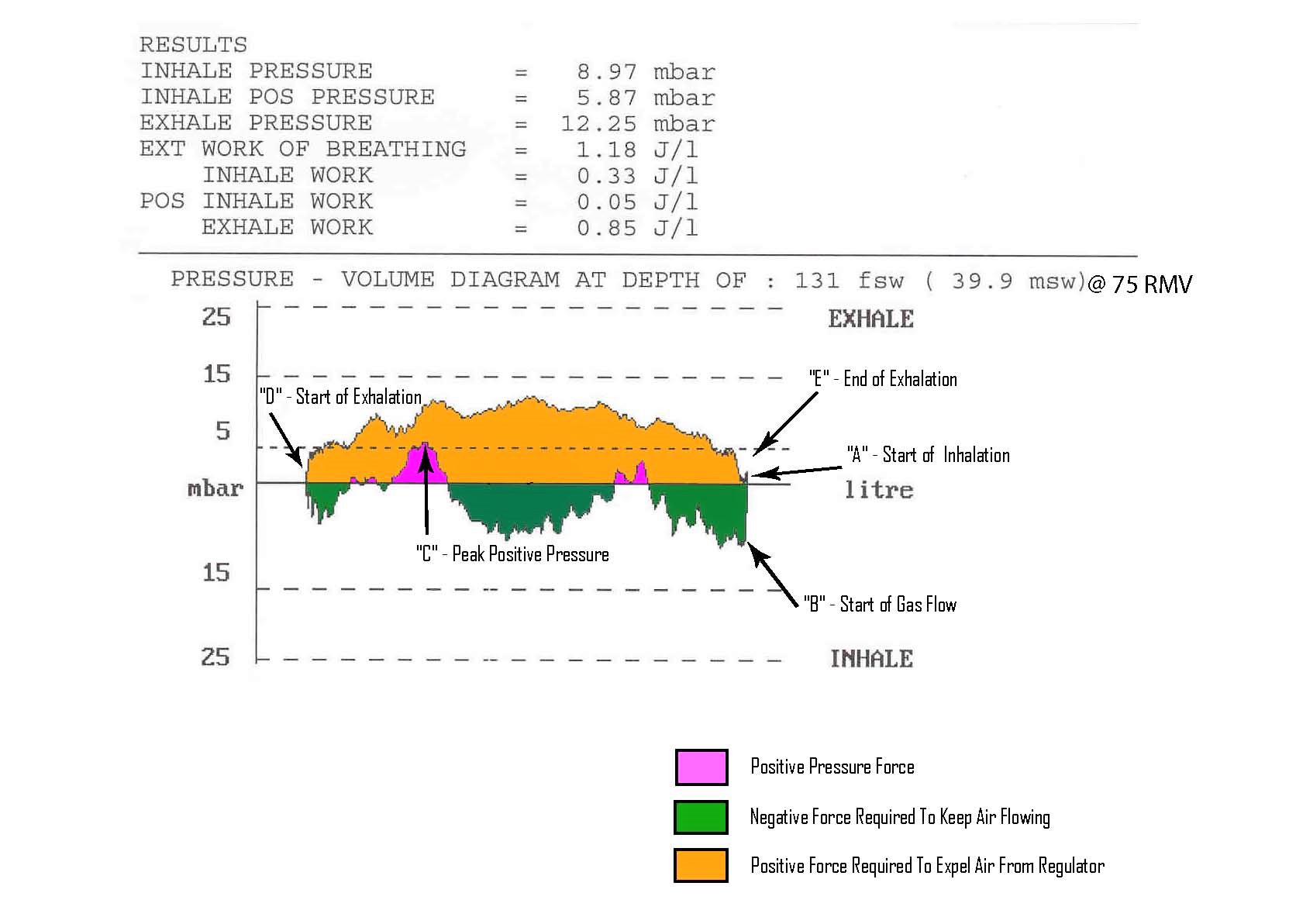
During breathing simulation, a very sensitive differential pressure transducer measures the oral positive and negative pressures (in the mouthpiece) within a 1 psig (68 mbar) range and transmits these pressures to the computer. At the same time, the linear transducer (piston position sensor) tells the computer where the piston is. The oral pressure is then plotted against the volume and the result is volume-averaged pressure. The lower the inhalation pressure, the easier the regulator delivers air. When the piston reaches the end of the inhalation stroke the exhalation cycle starts and the piston starts moving in the opposite direction and the exhalation cycle starts. Once again, the computer monitors the oral pressure and computes the volume average positive pressure. In reality, the computer constantly monitors the pressures, both positive and negative, and calculates the volume average pressure. While doing this, it also logs and prints out the overall work of breathing, peak positive and negative pressures as well other pertinent data. On average, the breathing machine is recording oral pressure at a sampling rate of around 700 samples per second or more.

Joules/Liter: The unit of measurement for breathing effort.

Millibars: Abbreviated as mbar. Used as the unit of pressure measurement positive or negative within the oral cavity, measured at the mouthpiece. 68 Millibars equals 1 pound per square inch pressure.

Work of Breathing: “WOB” the amount of effort to breath, expressed in Joule’s per liter abbreviated as J/L. The lower the J/L the better regulator breathes. External work of breathing is expressed on the ANSTI loop as external work (EXT). External work of breathing is the sum of the inhalation and exhalation effort expressed in J/L. External work is the work effort required to operate the breathing apparatus only.

Inhale Pressure: The peak inhalation pressure during the loop measured in mbar. During the inhalation cycle, there is usually a constant negative pressure. (Maximum allowable by CE Standards -25 millibars)

Inhale Positive Pressure: The peak positive pressure in mbar attained during the inhalation cycle. Positive pressure usually occurs during inhalation due to the venturi action. (Maximum allowable by CE Standards +5 millibars).

Exhalation Pressure: The peak pressure in millibars attained during the exhalation cycle in millibars. (Maximum allowable by CE Standards, +25 millibars).

Inhalation Work: The work effort during inhalation expressed in J/L.

Exhalation Work: The work effort during exhalation expressed in J/L.

Positive Inhalation Work: The work effort needed to counter the positive pressure delivered by the breathing equipment.

Virtually all scuba regulators incorporate what’s called a venturi assist. The venturi is usually a tube or directing vane that simply directs incoming air from the inlet valve at high velocity and funnels it into the oral tube, producing a low-pressure area that causes the diaphragm to move against the lever, assisting gas flow which in turn reduces inhalation work effort. In some regulators, the venturi can be too responsive resulting in positive pressure which in effect causes the regulator to force-feed air to the diver. A very slight amount of positive pressure can be beneficial at high work rates but positive pressure during normal breathing is uncomfortable and results in poor performance. The European Standard, EN-250, limits positive pressure to 5 mbar and 0.3 J/L.

Analyzing the Loop

The breathing loop in figure (1) is color coded to show a breakdown of the loop. The preceding explains in detail how to read the entire loop. The loop inhalation cycle starts at the point marked with “A”. The first part of the loop at point “A” shows where a negative pressure is drawn (start of inhale). At point “B”, the diaphragm activates the inlet valve and air starts to flow. The point from “A” to “B” is known as the cracking effort. In this loop particular loop, the cracking effort is around 8 millibars wich is typical of most good regulators. Next, moving to the left, the “green area” shows the inhalation air flowing. The closer to the zero line the trace stays, the lower the inhalation effort. The trace line then moves above the zero line “shaded in red”, this shows that the inlet valve has overshot the zero line, and allowed a slight positive pressure to develop. The valve then regains a fairly steady flow before going positive once again, peaking at just below 6 millibars as shown at point “C”. At point “D” exhalation starts and the area shaded orange shows the exhalation. The very highest part of the exhalation curve is the peak exhalation and in this case is around 12 millibars. This loop is typical, and it must be noted that that in this particular loop the breathing machine is ventilating at a rate of 75 liters per minute, which is considered extreme.

How much effort is needed to start gas flowing and keep it flowing, as well as how smooth the inhalation and exhalation is, all plays into how well a regulator breaths. So, what constitutes a top performance regulator for SCUBA divers? Before we can say what is good, we need to lay a few ground rules. A really good regulator should support the needs of a fit diver to the maximum depth of the dive. This can be a loaded statement because before you can say this you must quantify the need. CE European Testing sets the maximum breathing effort at 3 J/L. The 3 J/L is pretty high, but that is where they set the limit. This limit was originally set by the US Navy and was adopted by the Europeans. The Navy takes a slightly different approach; the Navy assigns goals. To be in a top performance category the Navy wants the regulator to have no greater than 1.37 J/L down to a depth of 198 feet seawater (FSW) when breathing at a work rate of 62.5 RMV or greater. Until recent years, very few regulators could meet this goal. The 1.37 goal was established because there were some regulators capable of this performance. Today there are many regulators that can perform below this level.

So now, we are back to what constitutes a great breathing regulator. It’s our opinion based on current regulator technology, the regulator should be capable of WOB under 2 J/L or less at 62.5 RMV down to the recreational depth limit of 130 fsw or the depth the user intends to use it to. For the “techi” people making deep air dives, it would be wise to use a regulator that is capable of below 2 J/L performance at 62.5 RMV to the maximum depth of the intended dive. Keep in mind regulator performance has gotten really good and this increase in performance makes diving safer and easier. Even a “hairy chested” deep sea diver in excellent condition diving to depths where WOB approaches 3 J/L leaves little reserve should things go side ways and heavy physical activity is encountered. Those diving into the ”outer limits” should go for the top performance regulators. In general, there is no excuse for the avid scuba diver not to have a good performing regulator, and not just one that squeaks in under the 3 Joule WOB limit. There are many good, inexpensive regulators capable of WOB performance under 2 J/L to depths of 130 FSW or deeper.

What is next? How much better will regulator performance get? Well, we have learned never to say never. Technology moves on and you can bet performance will keep inching forward, maybe not as fast as the PC, but things will keep rolling as long as the consumer keeps demanding it. There are certain physical limits to how much gas can flow at depth. Certainly the equipment can continue to get smaller and lighter and probably a lot more expensive.